Exemplary Tips About What Is The U Symbol In PCB

Decoding the "U"
1. Unraveling the Mystery of "U" on a Printed Circuit Board
Ever stared at a printed circuit board (PCB) and wondered what all those cryptic letters and numbers meant? You're not alone! Among the forest of components, you'll often spot a "U" symbol. It's not an alien marking or a secret code, although it might feel like it sometimes. Simply put, on a PCB, the "U" symbol designates an integrated circuit (IC). Think of it as the PCB's way of saying, "Hey, this is where the brains of the operation live!" These ICs are the workhorses that make all the electronic magic happen, performing everything from simple logic operations to complex signal processing.
Think of your PCB as a bustling city. The "U" marked ICs are the important municipal buildings like the city hall, the power plant, or the central communication hub. They're essential, and knowing where they are can be incredibly helpful when troubleshooting or designing. So, next time you see that "U," give it a little nod of respect — it's doing the heavy lifting!
The "U" itself doesn't specify what kind of IC it is. It could be a microcontroller, an op-amp, a memory chip, a logic gate, or a countless other possibilities. The specific function is determined by the part number printed next to the "U". This is why those long, seemingly random strings of characters are so important. They're the key to understanding exactly what that particular IC does. Treat them like the GPS coordinates to that building in your city, if you will.
You might be thinking, "Okay, I know it's an IC, but why 'U'?" Sadly, there's no super-exciting historical reason or ingenious mnemonic device. It's simply a convention that has evolved over time in the electronics industry. Some believe it's a shorthand for "Unit," but the exact origin is shrouded in a bit of mystery. What's important is that it's a universally understood identifier, making it easier for engineers and technicians worldwide to identify and work with ICs on PCBs.

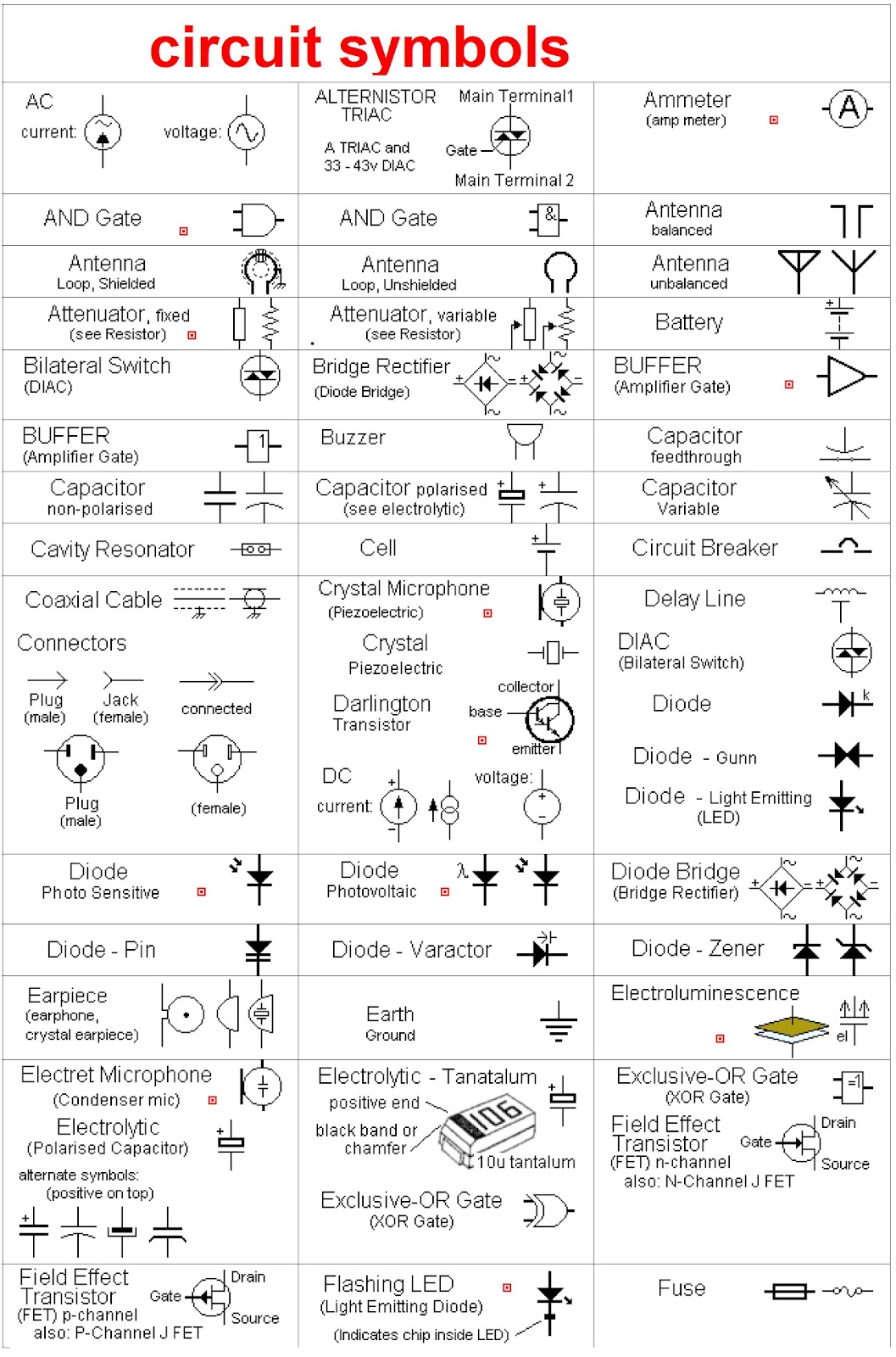
Circuit Schematic Symbols Chart
Why Knowing "U" Matters
2. The Practical Importance of Identifying Integrated Circuits
Now that you know "U" marks an IC, let's talk about why this seemingly small piece of information is actually quite powerful. Imagine your electronic gadget suddenly stops working. Where do you even begin to look? Well, knowing where the ICs are located can be a great starting point for troubleshooting. If you suspect a particular function is failing, you can focus your attention on the "U" marked IC responsible for that function.
Furthermore, if you're designing your own PCBs (which is an incredibly rewarding, if sometimes frustrating, hobby), understanding the "U" designation is essential for creating clear and understandable schematics and board layouts. It helps you organize your design and makes it easier for others (or even your future self) to understand how the circuit works. Trust me, your future self will thank you for properly labeling everything!
Beyond troubleshooting and design, knowing what ICs are present on a board can also be useful for reverse engineering or simply understanding the functionality of a device. By looking up the part numbers associated with the "U" symbols, you can quickly gain insights into the capabilities and limitations of the circuit. It's like having a roadmap to the inner workings of the electronic device.
Essentially, recognizing the "U" symbol provides a foundational understanding of PCB architecture. Its a little like knowing the alphabet before you start reading; you can't properly understand the bigger picture without grasping the significance of each individual IC and its placement within the circuit.

Beyond "U"
3. A Quick Guide to Other Letters and Numbers on PCBs
While "U" is definitely a key player, it's not the only symbol you'll encounter on a PCB. Here's a quick rundown of some other common designations:
- R: Resistor. These components resist the flow of electricity. Think of them as speed bumps for electrons.
- C: Capacitor. Capacitors store electrical energy. They're like tiny rechargeable batteries.
- L: Inductor. Inductors store energy in a magnetic field. They're often used in power supplies and filters.
- Q: Transistor. Transistors are semiconductor devices that can amplify or switch electronic signals. They're the fundamental building blocks of modern electronics.
- D: Diode. Diodes allow current to flow in only one direction. They're like one-way streets for electrons.
- J: Connectors. Used for external connections.
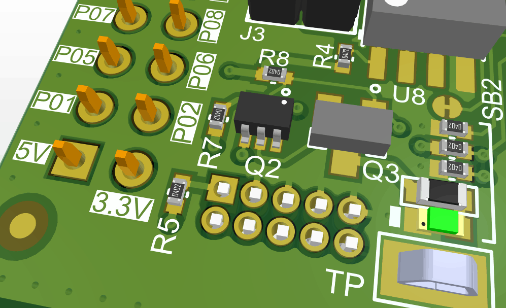
Each of these symbols is typically followed by a number (e.g., R1, C5, Q2), which uniquely identifies that specific component on the board. This numbering system is crucial for accurately locating and identifying components during assembly, testing, and repair. Its like having assigned parking spots for each electronic element.
Understanding these symbols, in addition to "U", will significantly improve your ability to read and interpret PCB layouts. It's like learning the street names in your city. The more you know, the easier it is to navigate.
Dont be intimidated by the seemingly complex world of PCB symbols and markings. With a little practice and a handy reference guide, you'll be deciphering those cryptic messages in no time. Just remember, every symbol has a purpose, and understanding them is the key to unlocking the secrets of electronics!

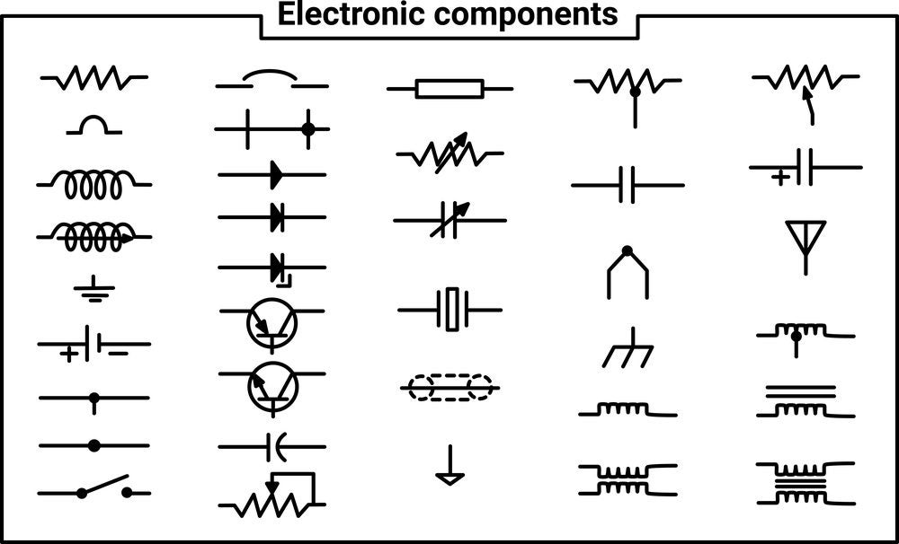
Pcb Design Part Information From Schematic Symbol Electrical
Demystifying Integrated Circuits
4. Exploring the World of ICs
Since "U" signifies an integrated circuit, it's worth diving a bit deeper into what these ICs actually are. An integrated circuit, also known as a microchip or simply a chip, is a miniature electronic circuit that contains a vast number of components, such as transistors, resistors, and capacitors, all fabricated on a single piece of semiconductor material, typically silicon. This integration allows for incredibly complex circuits to be packed into a tiny package.
ICs come in a wide variety of shapes, sizes, and functionalities. Some are designed for specific tasks, such as amplifying audio signals (op-amps), controlling motors (microcontrollers), or storing data (memory chips). Others are more general-purpose and can be programmed to perform a wide range of functions (field-programmable gate arrays, or FPGAs). The possibilities are truly endless.
The invention of the integrated circuit revolutionized the electronics industry. Before ICs, electronic circuits were built using discrete components, which were much larger, more expensive, and less reliable. The IC allowed for miniaturization, increased performance, and reduced cost, paving the way for the computers, smartphones, and other electronic devices we rely on today. It was a game changer!
So, when you see that "U" on a PCB, remember that it represents a marvel of engineering — a tiny chip packed with incredible complexity and capable of performing amazing feats of electronic wizardry. These ICs are the unsung heroes of the modern world, working tirelessly behind the scenes to make our lives easier and more connected.

Common PCB Component Codes Ultra Librarian
Practical Tips for Working with PCBs and "U" Symbols
5. Essential Advice for Handling and Identifying Components
Working with PCBs, especially if you're soldering or troubleshooting, requires a few precautions. Here are some tips to keep in mind:
- Static Electricity: ICs are sensitive to static electricity. Always ground yourself before handling PCBs or components. Use an anti-static wrist strap or touch a grounded metal object to discharge any static buildup.
- Heat: Excessive heat can damage ICs. When soldering, use a temperature-controlled soldering iron and apply heat for only a short period of time.
- Documentation: Keep good records of your PCB designs, including schematics and component lists. This will make it much easier to troubleshoot or modify your circuits in the future.
- Magnification: A magnifying glass or microscope can be invaluable for inspecting small components and solder joints.
- Datasheets: When working with ICs, always refer to the datasheet for detailed information about their specifications, pinouts, and operating conditions.
When identifying components based on the "U" symbol and its associated part number, double-check your information. Mistakes can happen, and misidentifying a component can lead to serious problems. Cross-reference the part number with online databases and datasheets to ensure you have the correct information.
If you're unsure about a particular component or circuit, don't hesitate to ask for help. There are many online forums and communities dedicated to electronics enthusiasts and professionals. Sharing your questions and experiences can be a great way to learn and improve your skills.
Remember safety is paramount! Always disconnect the power supply before working on any electronic circuit. And most importantly, have fun! Working with PCBs can be a rewarding and educational experience. Embrace the challenge, learn from your mistakes, and never stop exploring the fascinating world of electronics.
